Spanning-Tree (VOSS)

The switch supports Rapid Spanning Tree Protocol (RSTP) and Multiple Spanning Tree Protocol (MSTP).

Spanning Tree

Spanning Tree protocols detect and eliminate logical loops in a bridged or switched network. If multiple paths exist, the spanning Tree algorithm configures the network so that a bridge or device uses the root bridge path based on hop counts. Although link speed is taken into account, the path is based on the root bridge rather than on an optimized path. If that path fails, the protocol automatically reconfigures the network and makes another path active, thereby sustaining network operations. The switch supports RSTP and MSTP but can downgrade a port automatically if it receives an STP Bridge Protocol Data Unit (BPDU) from a switch that runs STP.

Note:

Spanning Tree is disabled on all Switched UNI (S-UNI) ports. The ports will move into forwarding state as soon as the physical port or VLACP or LACP comes up on the port. If the platform VLAN is associated to the S-UNI Service Instance Identifier (I-SID), then the S-UNI ports added to the platform VLAN will become the member of MSTP instances associated with the platform VLAN. To enable SLPP on the S-UNI ports, the platform VLAN must be associated with the S-UNI I-SID.

Spanning Tree Groups

Spanning Tree Groups (STGs) represent logical topologies. A topology is created based on bridge configuration values such as root bridge priority. In the case of multiple STGs, you can map a VLAN to the most appropriate logical topology in the physical network.

The switch supports Spanning Tree modes RSTP and MSTP. The default Spanning Tree mode is MSTP. The default STG is 0. In RSTP mode, all VLANs run in the default STG. In MSTP mode, you can create additional STGs by using the VLAN create command. The switch supports up to 64 STGs.

Although STP and MSTP are variations of the same Spanning Tree protocol, they communicate information differently. A switch in MSTI mode cannot recognize the Spanning Tree groups running on a chassis configured with STP. MSTP Spanning Tree groups are not the same as STP Spanning Tree groups. Using a switch in MSTP mode with a chassis in STP mode can create a loop in the network.

The root bridge for Rapid Spanning Tree Protocol (RSTP) and Multiple Spanning Tree Protocol (MSTP) is determined by comparing attributes of each bridge in the network.

The protocol considers bridge priority first. If more than one bridge has the same priority, then the protocol must consider the bridge ID. The bridge with the lowest ID becomes the root bridge. For MSTP, this bridge is called the Common and Internal Spanning Tree (CIST) Root because it is the root of the entire physical network.

In MSTP mode, you can create additional Spanning Tree instances, by using the VLAN command.

These instances, known as Multiple Spanning Tree Instances (MSTIs), can assign different priorities to switches. The MSTIs have different link costs or port priorities and as a result create separate logical topologies.

MSTP also allows the creation of MSTP regions. A region is a collection of switches sharing the same view of physical and logical topologies. For switches to belong to the same region, the following attributes must match:

• MSTP configuration ID selector

• MSTP configuration name

• MSTP configuration revision number

• VLAN instance mapping

Links connecting sections are called boundary ports. In a region, the boundary switch that contains the boundary port providing the shortest external path cost to the CIST Root is the CIST Regional Root.

STGs and VLANs

When you map VLANs to STGs, be aware that all links on the bridge belong to all STGs. Because each Spanning Tree group can differ in its decision to make a link forwarding or blocking, you must ensure that the ports you add to a VLAN are in the expected state.

Untagged ports can only belong to one VLAN and therefore can only belong to one STG. Tagged ports can belong to multiple VLANs and therefore to multiple STGs.
 

Fabric Connect Videos (by Ed Koehler)

Video 1 – Setting up a Fabric Connect Service Node

 https://youtu.be/FwtC0DhBjiI

Video 2 – Lab 2-Basic Fabric Connect show commands

 https://youtu.be/cYO5YTjnN6o

 Video 3 – Lab3-An IS-IS Link State Database Tour

 https://youtu.be/lBCN90Kc3Y0

Video 4 – Lab4-Setting up L2 Virtual Service Networks

 https://youtu.be/o3fuJb33HdQ

 Video 5 – Lab5-Setting up L3 Virtual Service Networks

 https://youtu.be/EPLSWSHhBYk

 Video 6 – Lab6-Connectivity Fault Management

 https://youtu.be/vdFc_5WNsxg

Stealth Networking

https://youtu.be/oTpFi8aT734


Testing Video Streams

Troubleshooting Video Traffic

Check for pause frames:

https://gtacknowledge.extremenetworks.com/articles/Solution/Pixelated-Jittery-or-Shuttering-Video-Streams-due-to-Flow-Control/?q=video+latency+EXOS&l=en_US&fs=Search&pn=1

IGMP Snooping:

https://gtacknowledge.extremenetworks.com/articles/Q_A/Which-command-is-used-to-enable-igmp-snooping/?q=igmp+snooping+exos&l=en_US&fs=Search&pn=1

https://gtacknowledge.extremenetworks.com/articles/How_To/How-to-enable-and-disable-IGMP-snooping-fast-leave-in-EXOS/?q=igmp+snooping+exos&l=en_US&fs=Search&pn=1

https://gtacknowledge.extremenetworks.com/articles/How_To/How-to-configure-switch-as-IGMP-querier/?q=igmp+snooping+exos&l=en_US&fs=Search&pn=1

https://gtacknowledge.extremenetworks.com/articles/How_To/How-to-configure-Static-IGMP/?q=igmp+snooping+exos&l=en_US&fs=Search&pn=1

Lab:

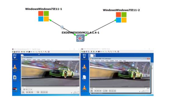
Simulate video by streaming a short .mp4 video sample using VLC and a virtual switch in GNS3.

cars

Sending PC sending stream using destination RTP/MPEG Transport Stream to address 224.0.0.1 port 5004.

Receiving PC play URL rtp://@224.0.0.1:5004.

Tip: On sending PC select Properties>Show Settings ALL and under Input / Codecs, Video codecs, FFmpeg enable Allow speed tricks and set Skip the loop filter for H.264 decoding to ALL. Save. This stops the sluggish behaviour on the playback from the sending PC. Even sluggish when plays back locally.

Transcoding options:

Select Activate Transcoding. Profile Video – H.264 + MP3 (MP4).

Miscellaneous Options:

Select Stream all elementary streams.


NSX

http://bradhedlund.com/?p=6626

https://www.vmware.com/products/nsx/nsx-hol.html

http://labs.hol.vmware.com/HOL/catalogs/catalog/681

http://docs.hol.vmware.com/

VMware Presents at Networking Field Day 15

https://pubs.vmware.com/NSX-6/index.jsp?topic=%2Fcom.vmware.nsx.admin.doc%2FGUID-3F96DECE-33FB-43EE-88D7-124A730830A4.html

https://blogs.vmware.com/networkvirtualization/2017/09/nsx-t-routing-where-you-need-it.html/

https://blogs.vmware.com/networkvirtualization/2018/01/nsx-t-routing-part-2.html/

https://datatracker.ietf.org/doc/draft-ietf-nvo3-geneve/

IP PBX

PBX:

AsteriskNOW is now FreePBX

Manage with FreePBX GUI by connecting browser to IP address of the AsteriskNow host machine.

Voicemail:

*97 = check voicemail

*98 = check any mailbox

Soft phone:

Products – X-Lite

https://support.counterpath.com/hc/en-us/articles/360001451094-How-do-you-set-QoS-for-Bria-4-5-in-Windows-

http://icanblink.com/

Tip: AsteriskNow acts as a bridge between two SIP phones. Use GNS3 wireshark to capture UDP traffic on either leg. Decode UTP traffic as RTP and Play Streams back using RTP Stream Analysis. It is possible to play back G711 codec.


Linux Static IP

## Configure eth0 #
# vi /etc/sysconfig/network-scripts/ifcfg-eth0

DEVICE=”eth0″
NM_CONTROLLED=”yes”
ONBOOT=yes
HWADDR=A4:BA:DB:37:F1:04
TYPE=Ethernet
BOOTPROTO=static
NAME=”System eth0″
UUID=5fb06bd0-0bb0-7ffb-45f1-d6edd65f3e03
IPADDR=192.168.1.44
NETMASK=255.255.255.0

## Configure Default Gateway #
# vi /etc/sysconfig/network

NETWORKING=yes
HOSTNAME=centos6
GATEWAY=192.168.1.1

## Restart Network Interface #

/etc/init.d/network restart

## Configure DNS Server #
# vi /etc/resolv.conf

nameserver 8.8.8.8      # Replace with your nameserver ip
nameserver 192.168.1.1  # Replace with your nameserver ip

Windows VM Mouse Pointer

To stabilize the two mouse pointers inside the Windows VM console add -usbdevice tablet in the options box in the Advanced settings>Additional settings screen.

Tip: Enable remote access so that can setup RDC to Windows VM.

Tip: EULA is for 90 days. User = IEUser and Password = Passw0rd!

Tip: Temporarily disable FW to prove ping test works.