Filter ACL on VOSS

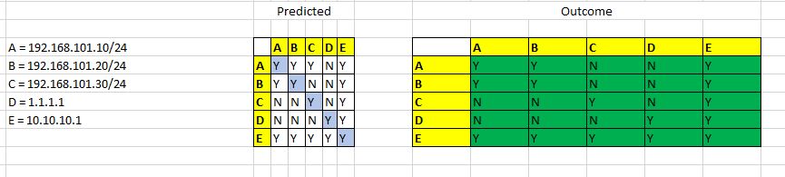
Following GNS3 simulation test to validate security ACL on VOSS. The goal is to only allow a range or specific IPs to communicate with a specific remote IP and to deny other IPs within the same VLAN subnet from communicating with other IPs inside and outside the VLAN.

# Filter Configuration

filter acl 101 type inVlan name “In vlan 101”
filter acl set 101 default-action deny
filter acl vlan 101 101

filter acl ace 101 1 name “arp req”
filter acl ace action 101 1 permit count
filter acl ace ethernet 101 1 ether-type eq arp
filter acl ace arp 101 1 operation eq arprequest
filter acl ace 101 1 enable

filter acl ace 101 2 name “arp resp”
filter acl ace action 101 2 permit count
filter acl ace ethernet 101 2 ether-type eq arp
filter acl ace arp 101 2 operation eq arpresponse
filter acl ace 101 2 enable

filter acl ace 101 3 name “192.168.101.10 to 192.168.101.20”
filter acl ace action 101 3 permit count
filter acl ace ethernet 101 3 ether-type eq ip
filter acl ace ip 101 3 src-ip eq 192.168.101.10
filter acl ace ip 101 3 dst-ip eq 192.168.101.20
filter acl ace 101 3 enable

filter acl ace 101 4 name “192.168.101.20 to 192.168.101.10”
filter acl ace action 101 4 permit count
filter acl ace ethernet 101 4 ether-type eq ip
filter acl ace ip 101 4 src-ip eq 192.168.101.20
filter acl ace ip 101 4 dst-ip eq 192.168.101.10
filter acl ace 101 4 enable

filter acl ace 101 5 name “Dst IP 10.10.10.1”
filter acl ace action 101 5 permit count
filter acl ace ethernet 101 5 ether-type eq ip
filter acl ace ip 101 5 dst-ip eq 10.10.10.1
filter acl ace 101 5 enable

filter acl ace 101 6 name “VLAN 190 Subnet”
filter acl ace action 101 6 deny count
filter acl ace ethernet 101 6 ether-type eq ip
filter acl ace ip 101 6 src-ip mask 192.168.101.0 24
filter acl ace 101 6 enable


GNS3 Lab Setup for Filter Test
Test Criteria / Outcome

Creating a VRF in VOSS

Assume you want to segment part of your network into its own isolated piece by using a VRF, how would you do this with VOSS?

ip vrf itstaff vrfid 1

vlan create 999 name “ITStaff” type port-mstprstp 0

vlan members add 999 1/8

interface vlan 999

vrf itstaff

ip address 192.168.99.2 255.255.255.0

exit

VRF “itstaff” includes VLAN 999 name “ITStaff” and is the only VLAN created so far in the VRF and the VRF has its own routing table.

VSP-1100:1(config)#show ip route vrf itstaff
************************************************************************************
Command Execution Time: Fri Apr 09 09:46:41 2021 UTC
************************************************************************************
=====================================================================================================
IP Route – VRF itstaff
=====================================================================================================
NH INTER
DST MASK NEXT VRF/ISID COST FACE PROT AGE TYPE PRF
—————————————————————————————————–
192.168.99.0 255.255.255.0 192.168.99.2 – 1 999 LOC 0 DB 0

1 out of 1 Total Num of Route Entries, 1 Total Num of Dest Networks displayed.
————————————————————————————————–
TYPE Legend:
I=Indirect Route, D=Direct Route, A=Alternative Route, B=Best Route, E=Ecmp Route,
U=Unresolved Route, N=Not in HW, F=Replaced by FTN, V=IPVPN Route, S=SPBM Route
PROTOCOL Legend:
v=Inter-VRF route redistributed
VSP-1100:1(config)#

Note: To test connectivity from the CLI with ping or traceroute remember to specify the VRF on the command line otherwise it will use the GRT and results will not be as expected.


Extreme Cloud IQ

Extreme Networks Cloud IQ onboarding of switches is quite straight forward and can be really useful for zero touch provisioning.

A few places to check if having problems connecting to Cloud IQ.

Add the correct device type and its serial number into Cloud IQ.

On the switch make sure it has the correct time otherwise it may have problems connecting to the server.

Enable DNS client on the switch so that the iqagent can resolve the FQDN of the server.

Make sure the switch can reach the internet and any Firewalls are not blocking the traffic.

https://extremeportal.force.com/ExtrArticleDetail?an=000079814&q=IQ%20AGENT%20FOR%20VOSS

https://extremeportal.force.com/ExtrArticleDetail?an=000079428

https://extremeportal.force.com/ExtrArticleDetail?an=000079403

Firewall Configuration Guides:

https://extremecloudiq.com/support/NL_GCP.html

EXOS Jumbo Support

Extreme Networks EXOS switches support jumbo frames. The default MTU size is 9216 bytes.

To configure the MTU size used for switching use the following command:

configure jumbo-frame-size <1523-9216>

To enable jumbo frames on all ports use the following command:

enable jumbo-frame ports all

To display jumbo frame support and size for a specific port:

show port 1:1 info detail

Output will show the following when enabled…

Jumbo: Enabled, MTU=9216