ISIS Accept Policy

Beginning in software release 4.1 for the VSP 4000/8000, 4.2.1 for the VSP 7200, and release 4.0 for the VSP 9000, IS-IS accept policies for IPv4 is introduced. Prior to this release, the ISIS IPv4 routes received over the SPB cloud are installed directly into the routing table. There is no ability to filter those routes and apply incoming route policies to them. Hence, networks that are being migrated from other routing protocols to ISIS/SPB are vulnerable to routing loops. ISIS accept policy functionality provides a way to avoid such loops.

You can create an IS-IS accept policy for the Global Routing Table (GRT) or a Virtual Routing and Forwarding (VRF) instance. You can create an IS-IS accept policy on a switch that operates at a global default level or for a specific advertising BEB. You can also use the filter mechanism for ISIS accept policies to redistribute routes between different VRFs, or between a VRF and the GRT.

ISIS policies can also use either a service instance identifier (ISID) or an ISID list to filter incoming traffic. For inter-VRF route redistribution, an ISID value of 0 represents the GRT. For inter-VRF route redistribution between VRFs, the ISID is the source VRF (or remote VRF).

You can filter traffic with ISIS accept policies by:

  •  advertising BEB (nick-name)
  •  ISID or ISID list (ISID take precedence over an ISID list)
  •  route-map

You can use IS-IS accept policies to apply at a global default level for all advertising Backbone Edge Bridges (BEBs) or for a specific advertising BEB.

IS-IS accept policies also allow you to use either a service instance identifier (ISID) or an ISID list to filter routes. The switch uses ISIDs to define Virtual Services Networks (VSNs). ISIDs identify and transmit virtualized traffic in an encapsulated SPBM frame. IS-IS accept policies can use ISIDs or ISID lists to filter the incoming virtualized traffic.

IS-IS accept policies can also apply route policies to determine what incoming traffic to accept into the routing table. With route policies the device can determine which routes to accept into the routing table based on the criteria you configure, which can give precedence to advertised routes from a particular protocol, route-source, route-type, or through other criteria.

ISISAccept.PNG

Note: The ERS 8800 does not support ISIS accept policies.

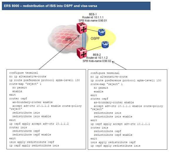
o There is no way to prevent one border router from accepting ISIS routes from the other border router

o The solution is to make OSPF preferred over ISIS by assigning ISIS a higher route preference over OSPF

We can now use OSPF accept policies to prevent one border router from accepting OSPF external routes from another

ERS8000ISISOSPF.PNG


VOSS ISIS-OSPF Lab 5 (Route Preference)

In some situations a router may advertise routes into ISIS from OSPF and overwrite routes which are in OSPF. One option is to increase the IP route preference of ISIS from default value 7 to 130 which is higher than OSPF routes making OSPF more favourable.

ip route preference protocol spbm-level1 130

Alternatively, if the platform allows, use ISIS accept policy to control what is learnt. Increasing the ip route preference is required with ERS 8000 as it does not support ISIS accept policies. It can also be useful to change the route preference during migrations and set back to default when required.

Also, when using IP shortcuts and redistribution of ISIS and OSPF it is recommended to disable ip alternative-routes.

no ip alternative-route


VOSS ISIS-OSPF Lab 4 (Block IST)

It is sometimes necessary to suppress the IST subnet when redistributing direct into ISIS on the cluster routers.

ip prefix-list “ist” 10.199.1.0/30 id 1 ge 30 le 30

route-map “suppress-ist” 1
no permit
enable
match network “ist”
route-map “suppress-ist” 2
permit
enable
exit

router isis
redistribute direct
redistribute direct route-map “suppress-ist”
redistribute direct enable
exit

isis apply redistribute direct

VOSS ISIS-OSPF Lab 3 (Announce Nets)

It is sometimes necessary to control which routes are advertised from OSPF into ISIS. This can be achieved by using a route-map when redistributing OSPF into ISIS.

ip prefix-list “access-nets” 0.0.0.0/0 id 2 ge 0 le 32
ip prefix-list “access-nets” 192.168.10.0/24 id 2 ge 24 le 24
ip prefix-list “access-nets” 192.168.20.0/24 id 2 ge 24 le 24

route-map “announce-access-nets” 1
permit
enable
match network “access-nets”
set injectlist “access-nets”
set metric-type type2
exit

router isis
redistribute ospf
redistribute ospf route-map “announce-access-nets”
redistribute ospf enable
exit

isis apply redistribute ospf

VOSS ISIS-OSPF Lab 2 (Reject Policy)

It is possible for the cluster routers to advertise an ISIS route into OSPF and overwrite the ISIS learnt routes on the peer router. To avoid this from occurring use a route map to reject routes from the peer OSPF router-ID.

R1 and R2:

route-map “reject” 1
no permit
enable
exit

R1:

router ospf
accept adv-rtr 10.255.0.2 enable route-map “reject”
exit

ip ospf apply accept adv-rtr 10.255.0.2

R2:

router ospf
accept adv-rtr 10.255.0.1 enable route-map “reject”
exit

ip ospf apply accept adv-rtr 10.255.0.1


VOSS ISIS-OSPF Lab 1 (OSPF LSDB)

Ever wondered why certain routes do not appear in the OSPF LSDB? The GRT shows routes but you do not see them when check the LSDB. In the example topology below R1 and R2 have learnt OSPF_INTRA (preference 20) and OSPF_E2 (preference 125) routes from R3. Checking the OSPF LSDB we see the ASExternal routes but not the OSPF_INTRA routes.

ISIS-OSPF

R3 has several loopback / CLIP addresses to simulate external networks. CLIP 2 192.168.10.1/24 and CLIP 4 192.168.30.1/24 have IP OSPF Enabled and CLIP 3 192.168.20.1/24 does not have IP OSPF Enabled. OSPF redistributes direct into OSPF.

This means we have some OSPF_INTRA routes and OSPF_E2 routes advertised by R3.

On R1 or R2 type show ip ospf lsdb adv-rtr 10.255.0.6 detail to see Router Link LSAs and ASExternal LSAs.

OSPF_INTRA


OSPF_E2


R1-GRT

SPB-PIM Gateway

Multicast over Fabric Connect cannot connect to a PIM router that is external to the SPB network.

When a receiver joins the SPB network for a specific group, the receiver must receive multicast streams in the neighboring multicast domains (PIM network). Similarly, a receiver in the neighboring multicast domain (PIM network) must receive multicast streams from sources in the SPB network. SPB-PIM Gateway (SPB-PIM GW) provides multicast inter-domain communication between an SPB network and a PIM network. SPB-PIM GW accomplishes this inter-domain communication across a special gateway VLAN. The gateway VLAN communicates with the PIM network through a subset of the full protocol messaging required for RFC 4601 compliance of a PIM interface, and translates the PIM network requirements into SPB language and vice versa.


Spanning-Tree (VOSS)

The switch supports Rapid Spanning Tree Protocol (RSTP) and Multiple Spanning Tree Protocol (MSTP).

Spanning Tree

Spanning Tree protocols detect and eliminate logical loops in a bridged or switched network. If multiple paths exist, the spanning Tree algorithm configures the network so that a bridge or device uses the root bridge path based on hop counts. Although link speed is taken into account, the path is based on the root bridge rather than on an optimized path. If that path fails, the protocol automatically reconfigures the network and makes another path active, thereby sustaining network operations. The switch supports RSTP and MSTP but can downgrade a port automatically if it receives an STP Bridge Protocol Data Unit (BPDU) from a switch that runs STP.

Note:

Spanning Tree is disabled on all Switched UNI (S-UNI) ports. The ports will move into forwarding state as soon as the physical port or VLACP or LACP comes up on the port. If the platform VLAN is associated to the S-UNI Service Instance Identifier (I-SID), then the S-UNI ports added to the platform VLAN will become the member of MSTP instances associated with the platform VLAN. To enable SLPP on the S-UNI ports, the platform VLAN must be associated with the S-UNI I-SID.

Spanning Tree Groups

Spanning Tree Groups (STGs) represent logical topologies. A topology is created based on bridge configuration values such as root bridge priority. In the case of multiple STGs, you can map a VLAN to the most appropriate logical topology in the physical network.

The switch supports Spanning Tree modes RSTP and MSTP. The default Spanning Tree mode is MSTP. The default STG is 0. In RSTP mode, all VLANs run in the default STG. In MSTP mode, you can create additional STGs by using the VLAN create command. The switch supports up to 64 STGs.

Although STP and MSTP are variations of the same Spanning Tree protocol, they communicate information differently. A switch in MSTI mode cannot recognize the Spanning Tree groups running on a chassis configured with STP. MSTP Spanning Tree groups are not the same as STP Spanning Tree groups. Using a switch in MSTP mode with a chassis in STP mode can create a loop in the network.

The root bridge for Rapid Spanning Tree Protocol (RSTP) and Multiple Spanning Tree Protocol (MSTP) is determined by comparing attributes of each bridge in the network.

The protocol considers bridge priority first. If more than one bridge has the same priority, then the protocol must consider the bridge ID. The bridge with the lowest ID becomes the root bridge. For MSTP, this bridge is called the Common and Internal Spanning Tree (CIST) Root because it is the root of the entire physical network.

In MSTP mode, you can create additional Spanning Tree instances, by using the VLAN command.

These instances, known as Multiple Spanning Tree Instances (MSTIs), can assign different priorities to switches. The MSTIs have different link costs or port priorities and as a result create separate logical topologies.

MSTP also allows the creation of MSTP regions. A region is a collection of switches sharing the same view of physical and logical topologies. For switches to belong to the same region, the following attributes must match:

• MSTP configuration ID selector

• MSTP configuration name

• MSTP configuration revision number

• VLAN instance mapping

Links connecting sections are called boundary ports. In a region, the boundary switch that contains the boundary port providing the shortest external path cost to the CIST Root is the CIST Regional Root.

STGs and VLANs

When you map VLANs to STGs, be aware that all links on the bridge belong to all STGs. Because each Spanning Tree group can differ in its decision to make a link forwarding or blocking, you must ensure that the ports you add to a VLAN are in the expected state.

Untagged ports can only belong to one VLAN and therefore can only belong to one STG. Tagged ports can belong to multiple VLANs and therefore to multiple STGs.


Fabric Connect Videos (by Ed Koehler)

Video 1 – Setting up a Fabric Connect Service Node

 https://youtu.be/FwtC0DhBjiI

Video 2 – Lab 2-Basic Fabric Connect show commands

 https://youtu.be/cYO5YTjnN6o

 Video 3 – Lab3-An IS-IS Link State Database Tour

 https://youtu.be/lBCN90Kc3Y0

Video 4 – Lab4-Setting up L2 Virtual Service Networks

 https://youtu.be/o3fuJb33HdQ

 Video 5 – Lab5-Setting up L3 Virtual Service Networks

 https://youtu.be/EPLSWSHhBYk

 Video 6 – Lab6-Connectivity Fault Management

 https://youtu.be/vdFc_5WNsxg

Stealth Networking

https://youtu.be/oTpFi8aT734